
Photos by magaieu
More than 50 % energy saving.
Higher speed than ever – in the water.
The basics of the „Inverse ship” was invented 100 years ago.

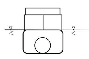
There were some patents from the 1915-2002 period: E.Court US 1,161,453; R.W. MILLER US 1,991,512; I.Y.TAM US 5,438,947; R.S. NOREK US 6,647,909,
that expired without large publicity.
The Fig. 1 and 2. show the key idea: All the moving water flow through the hull in an internal channel.
It would be easy to build an inverse ship if the diffuser is effective. The plain conical diffuser isn't effective enough. There are some uncontrollable motions generated in the practice.
Other problem: These patents had some similar channel (tunnel) inside of the ship (hull), but the location and design of the propulsion was different. The design of the propulsion is a key parameter to build a high speed and high efficiency ship. Their design wasn’t suitable for high speed because of the cavitation at the propeller or impeller.
Our calculations and tests show, that our design solved the problems above.
The theoretical speed limit of the ship is more than 500 km/h with our solution. More than 90% of the moving water flow through the ship's body in the Venturi-like channel.
It means: More than 90% of the motion energy of the water is controlled inside of the hull – instead of the spreading away by the waves.
There is no regular wave at the bow and at the stern of the hull.
While the inverse ship causes much less waves and swirl than most of the ships generate,
the energy (propulsion) need is less than it is usual for a regular ship with similar speed and mass.

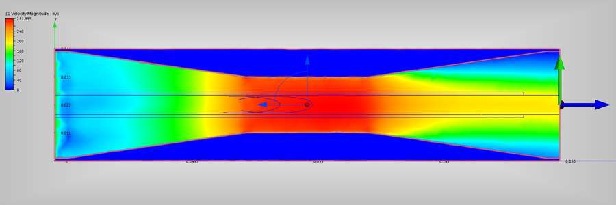
There were prepared 4 different hull by CAD and tested them by CFD program. The length is 198 mm and the initial and final diameters are 42 mm. The smallest diameter is 21 mm.
The propulsion is not showed at the left hand side. The initial speed, produced by the propulsion, is applied at the left side of the confuser.
See the velocity distribution diagram of the Hull 1 on the Fig. 3. It has conical confuser and empty conical diffuser. The initial water speed is 10 m/s.
The water with 1 bar static pressure and 12 oC temperature flows from left to right through the Venturi-like pipe system.

The scale shows the max speed inside (red color) is more than 21 m/s. The colors show the 1-14 m/s range of the exit flow. It is better than a direct water jet, but too much energy had been lost by the sped 10-14 m/s range. The Fig. 4. shows the results of the 150 m/s initial speed, and the Fig. 5. shows the results of the 500 m/s initial speed.
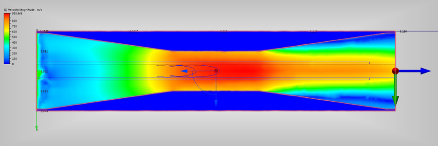
See the velocity distribution diagram of the Hull 2 on the Fig. 6. (10m/s), Fig. 7. (150m/s), Fig. 8. (500m/s) There is a conical control unit inside of the diffuser to help the speed homogenization.
PCT Search Report - PDF file
PCT Written Opinion - PDF file


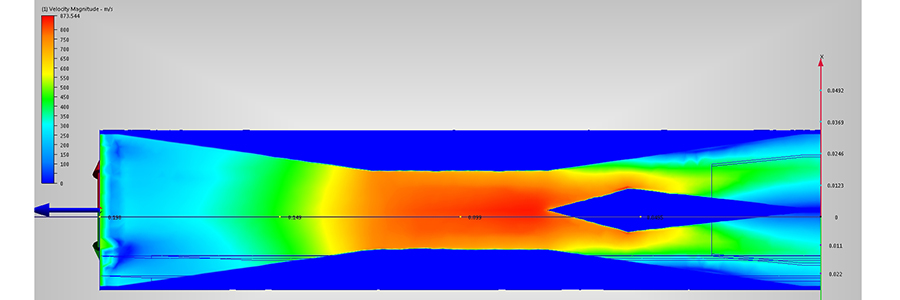
The speed distribution is much better than with the Hull 1 was. Less motion energy left the diffuser.
The better result was calculated with the Hull 3. This diffuser has some special deflectors inside.
See the velocity distribution diagram of the Hull 3 on the Fig. 9. (10m/s), Fig. 10. (150m/s), Fig. 11. (500m/s)
The speed homogenization is excellent.
PCT Search Report - PDF file
PCT Written Opinion - PDF file
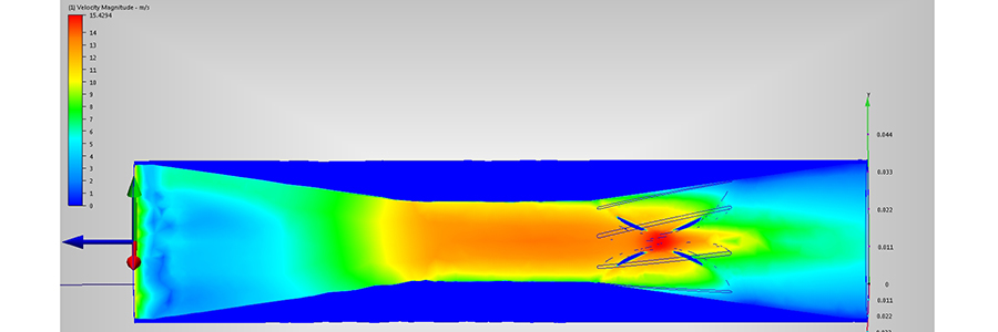


The Hull 3 can recover more than 90% of the motion energy of the water stream in to propulsion in the diffuser.
The 3D picture of the Hull 3 is on Fig. 12.

The Hull 4 is a reference calculation for 42 mm diameter of pipe.
Fig. 13. is for 10 m/s and Fig. 14. is for 500 m/s initial speed at the left side.


The parameters of the modeling were: water density=998.985 kg/m³, viscosity=0.001003 Pas, Specific heat=4182 J/kgK, Static pressure=1.0 bar, temperature=12 oC. No of iteration=100, material=steel.
We printed different hulls in 200-300 mm size and tested them in a test channel. The results are summarized in the video:
The size of the test channel: 4.0 x 0.4 x 0.2 m (L x W x H).
The first hull has electric motor – propeller propulsion. See Fig. 15. The mass of the hull is 165 g. The mass of the test cart is 562 g.
The nominal power of the motor is 31W, the efficiency is 45%.
The acceleration started at 0.5 m and the stop process started at 3.0 m distance.
The overall efficiency of the propulsion depended on the hull construction.
The propeller located in the convergent part of the channel. It drives all the moving water through the channel inside of the ship hull.
At the end of the channel there is a conical diffuser with a conical diffuser unit inside to make the water slow down. This is equivalent to the CFD Hull 2.
The cross section of the channel at the beginning and the end (and the ship in the water) is the same, so the speed of the water is same too.

On the video time 0:00 – 0:36 there are small waves, mainly caused by the fixing part of the cart.
There is no wave at the bow and only small wave at the stern. (The propulsion accelerated and moved the 3.4 times heavier cart. )
On the video time 0:37 – 0:43 and on the initial picture of the video there is a test without the conical unit inside of the diffuser.
This is equivalent to the CFD Hull 1.
The waves are larger and you can see some tangential vortex in the center of the diffuser and after it for some 50 mm distance.
This vortex was finished in a periodical swirl.
On the video time 0:44 – 1:00 there is a submarine hull (Fig. 16.) pulled by the cart (no internal propulsion).
There are significant waves and big flowing out from the channel. It is regular result with a submarine hull.

On the video time 1:02 – 1:21 there is a jet system with own propulsion. There are small waves at the bow, but there are significant waves at the stern. It looks like a water jet propulsion on a SWATH. The water jet transports away almost the half energy of the propulsion without any use. (Fig. 17.)

The cart (moving frame) generates some waves that you can see on Fig. 18. and Fig. 19.
This is the "basic noise" of the fixing part of the cart.
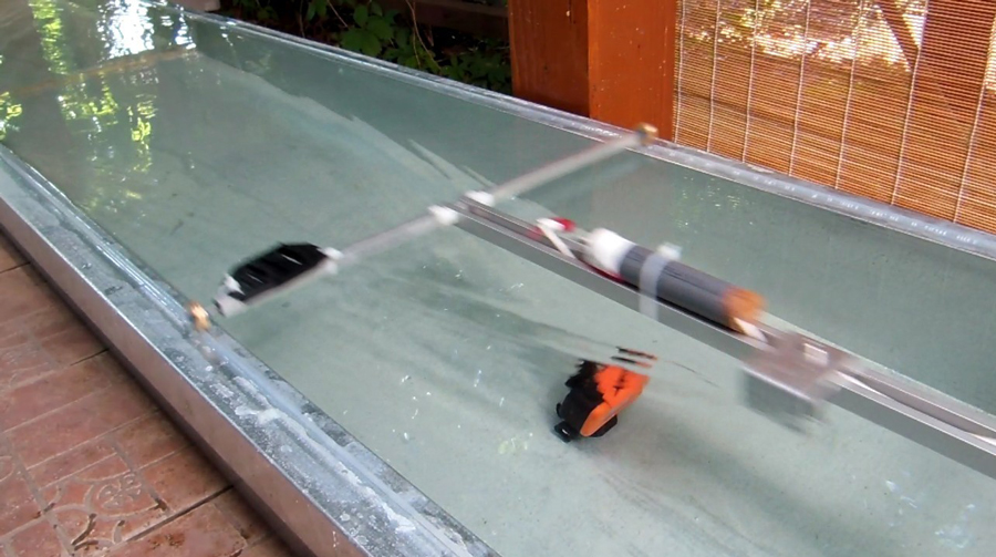
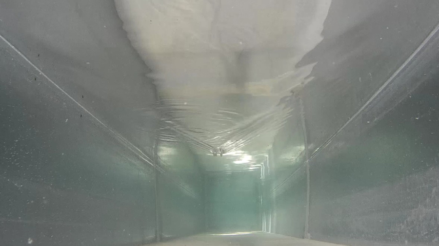
On the video time 1:23 – 1:54 there is a reference model motorboat with big waves and swirls.(Fig. 20.)

Real waves are generated by a 4.5 t motorboat with 190 kW engine. (Fig. 21.)

Crane barge or Ferry application on Fig. 22.

Internal layout Fig.23.

Inverse cover without change on hull Fig.24.

Submarine
SWATH hull
new class for the high speed marine transportation with high energy efficiency
WATERJET propulsion
Crane Barge
Ferry
Sailboat
Windsurf
75% REDUCTION in FUEL, CO2 and NOx - PDF file